Bending Radius and Light Loss in Optical Fiber
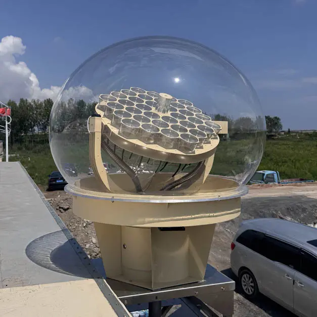
Field-deployed case study · Fiber-optic daylighting application
Bending Radius and Light Loss in Optical Fiber: Physical Principles and Engineering Limits
In optical fiber systems, bending is an unavoidable engineering consideration. Whether the fiber is used for data transmission or for daylighting and solar light guiding, any change in routing introduces bending, and therefore a relationship between bending radius and light loss. Understanding this relationship is essential for proper system design and long-term stability.
This article explains why optical fibers experience light loss when bent, starting from physical principles and extending to practical engineering constraints.
1. What Is Bending Radius in Optical Fiber
The bending radius refers to the radius of the circular arc formed when an optical fiber is bent. A tighter bend corresponds to a smaller radius, while a gentler curve corresponds to a larger radius.
In engineering practice, bending radius is usually defined in two categories:
- Short-term bending radius: the minimum radius allowed during installation or temporary handling
- Long-term bending radius: the minimum radius that can be maintained during continuous operation
These values are not merely recommendations. They represent physical limits related to optical attenuation, mechanical stress, and material durability.
2. Why Bending Causes Light Loss
Light propagation in optical fiber relies on total internal reflection. As long as the incident angle of the light remains above the critical angle at the core–cladding interface, the light is confined within the core and guided forward.
When a fiber is bent, this condition is locally disturbed. On the outer side of the bend, some rays experience a reduced incident angle, causing them to fall below the threshold for total internal reflection. As a result, part of the light leaks into the cladding or escapes the fiber entirely.
This type of loss, caused by visible or macroscopic bending, is known as macrobending loss. Bending also alters the modal distribution within the fiber, making higher-order modes more susceptible to leakage and scattering.
In silica-based fibers, bending introduces mechanical stress, which can slightly modify the local refractive index. This effect further increases attenuation in the bent region.
3. Relationship Between Bending Radius and Fiber Type
Different types of optical fiber respond differently to bending. Sensitivity to bending is influenced by factors such as core diameter, numerical aperture, cladding structure, and protective jacket materials.
Optical fibers used for daylighting applications typically have larger core diameters and higher numerical apertures than standard communication fibers. These characteristics allow them to accept light over a wider range of angles, but they do not eliminate bending-related losses.
For example, the low-OH high-purity silica fibers used in Dayluxa daylighting systems specify both short-term and long-term bending radius limits. These limits are determined through combined evaluation of optical attenuation, mechanical fatigue, and long-term operational stability.
4. Why Long-Term Bending Is More Critical Than Short-Term Bending
A common misconception is that if no immediate problem appears during installation, bending will not affect performance later. In reality, sustained bending at a small radius poses a greater long-term risk.
Continuous mechanical stress can promote slow growth of micro-cracks within the silica structure. Under thermal cycling and prolonged loading, attenuation may increase gradually rather than abruptly.
In daylighting systems, this degradation is often difficult to detect. The system continues to deliver light, but output levels may decline over months or years, reducing overall illumination effectiveness.
5. Practical Engineering Guidelines
Several general principles are commonly applied in optical fiber system design:
- Fixed routing should always comply with long-term bending radius limits
- Reducing the number of bends improves long-term system stability
- Bends closer to the light source have a greater impact on total transmitted flux
- Optical loss is cumulative; multiple minor bends can produce significant attenuation
6. Special Considerations for Daylighting Optical Fibers
In communication systems, optical loss can often be compensated through amplification or signal processing. In contrast, daylighting systems based on real solar input have no such compensation mechanism.
Every unit of optical loss directly reduces usable illumination. For this reason, daylighting fiber systems impose stricter constraints on bending radius, routing geometry, and material selection than many other optical applications.
Conclusion
Bending radius is not merely a mechanical specification. It is a key parameter that determines optical performance and service life in fiber systems. Understanding how bending leads to light loss is essential for designing reliable and durable solutions.
Respecting bending radius limits ultimately means respecting the physical laws that govern how light propagates through optical fiber.